


invented by: Ewald Georg von Kleist
A capacitor (formerly known as condenser) is a device for storing electric charge. The forms of practical capacitors vary widely, but all contain at least two conductors separated by a non-conductor. Capacitors used as parts of electrical systems, for example, consist of metal foils separated by a layer of insulating film.
A capacitor is a passive electronic component consisting of a pair of conductors separated by a dielectric (insulator). When there is a potential difference (voltage) across the conductors, a static electric field develops across the dielectric, causing positive charge to collect on one plate and negative charge on the other plate. Energy is stored in the electrostatic field. An ideal capacitor is characterized by a single constant value, capacitance, measured in farads. This is the ratio of the electric charge on each conductor to the potential difference between them.
Capacitors are widely used in electronic circuits for blocking direct current while allowing alternating current to pass, in filter networks, for smoothing the output of power supplies, in the resonant circuits that tune radios to particular frequencies and for many other purposes.
The capacitance is greatest when there is a narrow separation between large areas of conductor, hence capacitor conductors are often called "plates," referring to an early means of construction. In practice the dielectric between the plates passes a small amount of leakage current and also has an electric field strength limit, resulting in a breakdown voltage, while the conductors and leads introduce an undesired inductance and resistance.
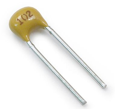
In electronics we need capacitor in almost every circuit, The cylindrical capacitor are rated exactly on their cover. But the ceramic and other capacitor have some code which must be known to us for reading the capacitor.
Generally, the actual values of Capacitance, Voltage or Tolerance are marked onto the body of the capacitors in the form of alphanumeric characters. However, when the value of the capacitance is of a decimal value problems arise with the marking of a "Decimal Point" as it could easily not be noticed resulting in a misreading of the actual value. Instead letters such as p (pico) or n (nano) are used in place of the decimal point to identify its position and the weight of the number. For example, a capacitor can be labelled as, n47 = 0.47nF, 4n7 = 4.7nF or 47n = 47nF. Also, sometimes capacitors are marked with the capital letter K to signify a value of one thousand pico-Farads, so for example, a capacitor with the markings of 100K would be 100 x 1000pF or 100nF.
To reduce the confusion regarding letters, numbers and decimal points, an International colour coding scheme was developed many years ago as a simple way of identifying capacitor values and tolerances. It consists of coloured bands (in spectral order) known commonly as the Capacitor Colour Code system and whose meanings are illustrated below:


Capacitor Voltage Reference
Type J - Dipped Tantalum Capacitors.
Type K - Mica Capacitors.
Type L - Polyester/Polystyrene Capacitors.
Type M - Electrolytic 4 Band Capacitors.
Type N - Electrolytic 3 Band Capacitors.
An example of the use of capacitor colour codes is given as:

The Capacitor Colour Code system was used for many years on unpolarised polyester and mica moulded capacitors. This system of colour coding is now obsolete but there are still many "old" capacitors around. Nowadays, small capacitors such as film or disk types conform to the BS1852 Standard and its new replacement, BS EN 60062, were the colours have been replaced by a letter or number coded system. The code consists of 2 or 3 numbers and an optional tolerance letter code to identify the tolerance. Where a two number code is used the value of the capacitor only is given in picofarads, for example, 47 = 47 pF and 100 = 100pF etc. A three letter code consists of the two value digits and a multiplier much like the resistor colour codes in the resistors section. For example, the digits 471 = 47*10 = 470pF. Three digit codes are often accompanied by an additional tolerance letter code as given below.

Consider the capacitor below:
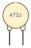
The capacitor on the left is of a ceramic disc type capacitor that has the code 473J printed onto its body. Then the 4 = 1st digit, the 7 = 2nd digit,
the 3 is the multiplier in pico-Farads, pF and the letter J is the tolerance and this translates to:
47pF * 1,000 (3 zero's) = 47,000 pF , 47nF or 0.047 uF
the J indicates a tolerance of +/- 5%
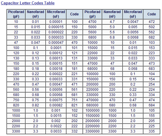
Then by just using numbers and letters as codes on the body of the capacitor we can easily determine the value of its capacitance either in Pico-farad's, Nano-farads or Micro-farads and a list of these "international" codes is given in the following table along with their equivalent capacitances.


Oh dear, more plagiarised content, I guess Google will just have to shut you down.
ReplyDeleteHello,
DeleteAt the time I publish this article I didn't know anything like plagiarism exists. These article was just for my college friends so that they can read the information wherever they are.
Well thank you for comment, now I know something about plagiarism.
Thanks
very helpfull for students...
ReplyDeleteVery useful for Electronics and Communication engineering student.
ReplyDeleteThanks for Comment.
DeleteIf you have any other problem, or suggestion please leave a comment.
We have a big team working in collaboration to help students and industry persons.
Thanks again
high voltage film capacitors I think this is an informative post and it is very useful and knowledgeable. therefore, I would like to thank you for the efforts you have made in writing this article.
ReplyDelete