Search This Blog

Most Viewed

Sunday, July 31, 2011

Reference Books For ECE and GATE Preparations


Reference Books for ECE 


Linear Algebra, Numerical Methods,Transform Theory
Higher Engineering Mathematics by B.S.Grewal


Calculus, Differential equations, Complex variables
Intermediate Mathematics, S.chand publications by B.V.Sastry , K.Venkateswarlu ( if i remember ) both the volumes.


Probability and Statistics
Probability , statistics and queuing theory by S.C.Gupta & V.K.Kapoor


Networks: Network graphs

Network Analysis by Van Valkenburg
Network Theory by Alexander Sadiku, UA Bakshi
Network Theory by Shaum’s outline, Robbins and Miller


Electronic Devices

Electronic Devices and Circuits by Boylestead
Solid State Electronic Devices by Benjamin G Streetman
Integrated electronics by Milman Halkias
Electronic Devices and Circuits by David A Bell
Integrated Circuits: Sedra Smith, K.R. Botkar
Electronic Principals by Malvino


Analog and Digital Circuits 

Engineering Circuit Analysis Hayt & Kemmerly
Electric Circuits by Joseph A. Edminister
Fundamentals of Electric Circuits – Sadiku
Electronic Circuit Analysis by Donald Neamen
Electronic Devices and Circuits by Boylestead
Micro Electronic Circuits by Sedra & Smith
Digital Circuits Anand Kumar, Morris Mano


Signals and Systems

Signals and System by Oppenham and Schiener
Signals and System: by Schaum Series, Willsky & Nacob
Signals and System by Sanjay Sharma


Control Systems

Control Systems by Ogatta,Kuo
Linear Control Systems by B.S Manke


Communications

Communication Systems by Simon Haykin
Principle of Communication System by B. P. Lathi
Principle of Communication System by Taub & Schilling
Communication Systems by Carlson
Communication Systems by Sanjay Sharma


Electromagnetics

Electromagnetic Waves & Radiating Systems by Hayt, JD Kraus
Elements of Electromagnetics by Sadiku
Electromagnetics by J.D.Kraus
Engineering Applications of Electromagnetic Theory by Liao


Few other useful books for GATE ECE preparation:


Gate 2010 by R.S. Kanodia (for questions only)
Previous GATE Question papers(Made Easy Publishers,GK publishers etc)
Previous Engg Services question papers(Made Easy Publishers)
Aptitude Test-D R Choudhary
GATE Physics Self Study Book by Surekha Tomar
Multiple Choice Questions with Explainatory Answers by UPKAR Publication , Agra


http://www.inspirenignite.com/gate-study-material-for-ece/


Wednesday, July 27, 2011

Great Invention: Light Bulb


Light Bulb by Thomas Alva Edison in 1879:


Milestones:


1850 Joseph W. Swan began working on a light bulb using carbonized paper filaments
1860 Swan obtained a UK patent covering a partial vacuum, carbon filament incandescent lamp
1877 Edward Weston forms Weston Dynamo Machine Company, in Newark, New Jersey.
1878 Thomas Edison founded the Edison Electric Light Company
1878 Hiram Maxim founded the United States Electric Lighting Company
1878 205,144 William Sawyer and Albon Man 6/18 for Improvements in Electric Lamps
1878 Swan receives a UK patent for an improved incandescent lamp in a vacuum tube
1879 Swan began installing light bulbs in homes and landmarks in England.
1880 223,898 Thomas Edison 1/27 for Electric Lamp and Manufacturing Process
1880 230,309 Hiram Maxim 7/20 for Process of Manufacturing Carbon Conductors
1880 230,310 Hiram Maxim 7/20 for Electrical Lamp
1880 230,953 Hiram Maxim 7/20 for Electrical Lamp
1880 233,445 Joseph Swan 10/19 for Electric Lamp
1880 234,345 Joseph Swan 11/9 for Electric Lamp
1880 Weston Dynamo Machine Company renamed Weston Electric Lighting Company
1880 Elihu Thomson and Edwin Houston form American Electric Company
1880 Charles F. Brush forms the Brush Electric Company
1881 Joseph W. Swan founded the Swan Electric Light Company
1881 237,198 Hiram Maxim 2/1 for Electrical Lamp assigned to U.S. Electric Lighting Company
1881 238,868 Thomas Edison 3/15 for Manufacture of Carbons for Incandescent Lamps
1881 247,097 Joseph Nichols and Lewis Latimer 9/13 for Electric Lamp
1881 251, 540 Thomas Edison 12/27 for Bamboo Carbons Filament for Incandescent Lamps
1882 252,386 Lewis Latimer 1/17 for Process of Manufacturing Carbons assigned to U.S. E. L. Co.
1882 Edison's UK operation merged with Swan to form the Edison & Swan United Co. or "Edi-swan"
1882 Joesph Swan sold his United States patent rights to the Brush Electric Company
1883 American Electric Company renamed Thomson-Houston Electric Company
1884 Sawyer & Man Electric Co formed by Albon Man a year after William Edward Sawyer death
1886 George Westinghouse formed the Westinghouse Electric Company
1886 The National Carbon Co. was founded by the then Brush Electric Co. executive W. H. Lawrence
1888 United States Electric Lighting Co. was purchased by Westinghouse Electric Company
1886 Sawyer & Man Electric Co. was purchased by Thomson-Houston Electric Company
1889 Brush Electric Company merged into the Thomson-Houston Electric Company
1889 Edison Electric Light Company consolidated and renamed Edison General Electric Company.
1890 Edison, Thomson-Houston, and Westinghouse, the "Big 3" of the American lighting industry.
1892 Edison Electric Light Co. and Thomson-Houston Electric Co. created General Electric Co.
light bulb, electric lamp, incandescent lamp, electric globe, Thomas Edison, Joseph Swan, Hiram Maxim, Humphrey Davy, James Joule, George Westinghouse, Charles Brush, William Coolidge, invention, history, inventor of, history of, who invented, invention of, fascinating facts.

Construction:


Incandescent light bulbs consist of a glass enclosure (the envelope, or bulb) with a filament of tungsten wire inside the bulb, through which an electric current is passed. Contact wires and a base with two (or more) conductors provide electrical connections to the filament. Incandescent light bulbs usually contain a stem or glass mount anchored to the bulb's base that allows the electrical contacts to run through the envelope without gas/air leaks. Small wires embedded in the stem in turn support the filament and/or its lead wires. The bulb is filled with an inert gas such as argon to reduce evaporation and prevent oxidation of the filament.
An electric current heats the filament to typically 2,000 to 3,300 K (3,140 to 5,480 °F)), well below tungsten's melting point of 3,695 K (6,191 °F). Filament temperatures depend on the filament type, shape, size, and amount of current drawn. The heated filament emits light that approximates a continuous spectrum. The useful part of the emitted energy is visible light, but most energy is given off as heat in the near-infrared wavelengths.
Three-way light bulbs have two filaments and three conducting contacts in their bases. The filaments share a common ground, and can be lit separately or together. Common wattages include 30–70–100, 50–100–150, and 100–200–300, with the first two numbers referring to the individual filaments, and the third giving the combined wattage.
While most light bulbs have clear or frosted glass, other kinds are also produced, including the various colors used for Christmas tree lights and other decorative lighting. Neodymium-containing glass is sometimes used to provide a more natural-appearing light.


Many arrangements of electrical contacts are used. Large lamps may have a screw base (one or more contacts at the tip, one at the shell) or a bayonet base (one or more contacts on the base, shell used as a contact or used only as a mechanical support). Some tubular lamps have an electrical contact at either end. Miniature lamps may have a wedge base and wire contacts, and some automotive and special purpose lamps have screw terminals for connection to wires. Contacts in the lamp socket allow the electric current to pass through the base to the filament. Power ratings for incandescent light bulbs range from about 0.1 watt to about 10,000 watts.
The glass bulb of a general service lamp can reach temperatures between 200 and 260 °C (392 and 500 °F). Lamps intended for high power operation or used for heating purposes will have envelopes made of hard glass or fused quartz.

http://en.wikipedia.org/wiki/Incandescent_light_bulb
http://www.ideafinder.com/history/inventions/lightbulb.htm


I Networks: Network Theorems: Thevenin's Theorem


Statement of Thevenin's Theorem:

A general statement of Thevenin's Theorem is that any linear active network consisting of independent and or dependent voltage and current source and linear bilateral network element can be replaced by an equivalent circuit consisting of a voltage source in series with a resistance, the voltage source is being the open circuited voltage across the open circuited load terminals and the resistance being the internal resistance of the source network looking through the open circuited load terminals. 

or we can say that

Any two terminal bilateral linear d.c. circuit can be replaced by an equivalent circuit consisting of a voltage source and a series resistor.

The theorem was first discovered by German scientist Hermann von Helmholtz in 1853, but was then rediscovered in 1883 by French telegraph engineer Léon Charles Thévenin (1857–1926).


Steps for Solving a Network Utilizing Thevenin's Theorem:


I. Remove the load resistance Rl and find the open circuit voltage Voc across the open circuited load terminals.
II. Deactivate the constant sources ( for voltage source, remove it by internal resistance which is usually zero, and for current source remove it by internal resistance which is usually infinite, so voltage source is shorted and current source is opened ) of the source side looking through the open circuited load terminals. Let this resistance be Rth.
III. Obtain Thevenin's equivalent circuit by placing Rth in series with Voc.
IV. Reconnect Rl across the load terminals.

The Load current I  can be given as:
Voc/(Rth+Rl)

Tuesday, July 5, 2011

GATE 2012 Syllabus For Eelctronics and Communication

Here Is the GATE 2012 Syllabus for Electronics & Communication Engineering.

Engineering Mathematics

Linear Algebra:
Matrix Algebra, Systems of linear equations, Eigen values and eigen vectors.

Calculus:
Mean value theorems, Theorems of integral calculus, Evaluation of definite and improper integrals, Partial Derivatives, Maxima and minima, Multiple integrals, Fourier series. Vector identities, Directional derivatives, Line, Surface and Volume integrals, Stokes, Gauss and Green?s theorems.

Differential equations:
First order equation (linear and nonlinear), Higher order linear differential equations with constant coefficients, Method of variation of parameters, Cauchy?s and Euler?s equations, Initial and boundary value problems, Partial Differential Equations and variable separable method.

Complex variables:
Analytic functions, Cauchy's integral theorem and integral formula, Taylor's and Laurent' series, Residue theorem, solution integrals.

Probability and Statistics:
Sampling theorems, Conditional probability, Mean, median, mode and standard deviation, Random variables, Discrete and continuous distributions, Poisson, Normal and Binomial distribution, Correlation and regression analysis.

Numerical Methods:
Solutions of non-linear algebraic equations, single and multi-step methods for differential equations.

Transform Theory:
 Fourier transform, Laplace transform, Z-transform.


Electronics & Communication Engineering

Networks:
Network graphs: matrices associated with graphs; incidence, fundamental cut set and fundamental circuit matrices. Solution methods: nodal and mesh analysis. Network theorems: superposition, Thevenin and Norton?s maximum power transfer, Wye-Delta transformation. Steady state sinusoidal analysis using phasors. Linear constant coefficient differential equations; time domain analysis of simple RLC circuits, Solution of network equations using Laplace transform: frequency domain analysis of RLC circuits. 2-port network parameters: driving point and transfer functions. State equations for networks.

Electronic Devices: 
Energy bands in silicon, intrinsic and extrinsic silicon. Carrier transport in silicon: diffusion current, drift current, mobility, and resistivity. Generation and recombination of carriers. p-n junction diode, Zener diode, tunnel diode, BJT, JFET, MOS capacitor, MOSFET, LED, p-I-n and avalanche photo diode, Basics of LASERs. Device technology: integrated circuits fabrication process, oxidation, diffusion, ion implantation, photolithography, n-tub, p-tub and twin-tub CMOS process.

Analog Circuits:
Small Signal Equivalent circuits of diodes, BJTs, MOSFETs and analog CMOS. Simple diode circuits, clipping, clamping, rectifier. Biasing and bias stability of transistor and FET amplifiers. Amplifiers: single-and multi-stage, differential and operational, feedback, and power. Frequency response of amplifiers. Simple op-amp circuits. Filters. Sinusoidal oscillators; criterion for oscillation; single-transistor and op-amp configurations. Function generators and wave-shaping circuits, 555 Timers. Power supplies.

Digital circuits:
Boolean algebra, minimization of Boolean functions; logic gates; digital IC families (DTL, TTL, ECL, MOS, CMOS). Combinatorial circuits: arithmetic circuits, code converters, multiplexers, decoders, PROMs and PLAs. Sequential circuits: latches and flip-flops, counters and shift-registers. Sample and hold circuits, ADCs, DACs. Semiconductor memories. Microprocessor(8085): architecture, programming, memory and I/O interfacing.

Signals and Systems:
Definitions and properties of Laplace transform, continuous-time and discrete-time Fourier series, continuous-time and discrete-time Fourier Transform, DFT and FFT, z-transform. Sampling theorem. Linear Time-Invariant (LTI) Systems: definitions and properties; causality, stability, impulse response, convolution, poles and zeros, parallel and cascade structure, frequency response, group delay, phase delay. Signal transmission through LTI systems.

Control Systems:
Basic control system components; block diagrammatic description, reduction of block diagrams. Open loop and closed loop (feedback) systems and stability analysis of these systems. Signal flow graphs and their use in determining transfer functions of systems; transient and steady state analysis of LTI control systems and frequency response. Tools and techniques for LTI control system analysis: root loci, Routh-Hurwitz criterion, Bode and Nyquist plots. Control system compensators: elements of lead and lag compensation, elements of Proportional-Integral-Derivative (PID) control. State variable representation and solution of state equation of LTI control systems.

Communications:
Random signals and noise: probability, random variables, probability density function, autocorrelation, power spectral density. Analog communication systems: amplitude and angle modulation and demodulation systems, spectral analysis of these operations, superheterodyne receivers; elements of hardware, realizations of analog communication systems; signal-to-noise ratio (SNR) calculations for amplitude modulation (AM) and frequency modulation (FM) for low noise conditions. Fundamentals of information theory and channel capacity theorem. Digital communication systems: pulse code modulation (PCM), differential pulse code modulation (DPCM), digital modulation schemes: amplitude, phase and frequency shift keying schemes (ASK, PSK, FSK), matched filter receivers, bandwidth consideration and probability of error calculations for these schemes. Basics of TDMA, FDMA and CDMA and GSM.

Electromagnetics:
Elements of vector calculus: divergence and curl; Gauss? and Stokes? theorems, Maxwell?s equations: differential and integral forms. Wave equation, Poynting vector. Plane waves: propagation through various media; reflection and refraction; phase and group velocity; skin depth. Transmission lines: characteristic impedance; impedance transformation; Smith chart; impedance matching; S parameters, pulse excitation. Waveguides: modes in rectangular waveguides; boundary conditions; cut-off frequencies; dispersion relations. Basics of propagation in dielectric waveguide and optical fibers. Basics of Antennas: Dipole antennas; radiation pattern; antenna gain.

Embedded Projects For Final Year Electronics & Communication

Here are some easy an very illustrative project for the Electronics and Communication Final Year. And most of them are also available here for the order also. So enjoy,

  1.  Auto Control of three phase Induction motor (AT89S52)
  2.  Automatic College Bell (AT89S8252 & DS1307)
  3.  Automatic plant Irrigation (AT89C2051)
  4.  Automatic Room light Controller with Visitor Counter (AT89S52)
  5.  BIOMEDICAL MONITORING SYSTEM (AT89C2051 + TX/RX)
  6.  Device control through Bluetooth from Symbian OS Mobiles
  7.  Device Controlling through PC (Visual Basic)
  8.  Digital Calendar (AT89C2051)
  9.  Digital Countdown Timer (AT89C2051)
  10.  Digital IC Tester for 74 series
  11.  Digital Visitor Counter (AT89C2051)
  12.  DS1620 Based Temperature Controller (AT89S52)
  13.  DS1820 Based High Precision Temperature Indicator
  14.  Electronic Cash Register (ECR)
  15.  Electronic Voting Machine (AT89S8252)
  16.  Electronics Components Tester (AT89C52)
  17.  Fingerprint Based Electronic Voting Machine
  18.  FingerPrint Based Security System
  19.  Fire Fighting Robot (AT89S52)
  20.  Gates Emulator (AT89C2051)
  21.  Home Security System(AT89S52)
  22.  Infrared Interruption counter (AT89C2051)
  23.  InfraRed Remote Switch (6 devices + 1 fan) -AT89S52
  24.  InfraRed Remote Switch (AT89C2051)
  25.  Interactive Voice Response System For College Automation (IVRS)
  26.  Line Following Robot (AT89C2051)
  27.  Microcontroller Based Caller ID (AT89C2051)
  28.  Microcontroller Based Digital Clock with Alarm
  29.  Microcontroller Based Digital code Lock (AT89C2051)
  30.  Multipattern Running Lights (AT89C2051)
  31.  Parallel Telephone with auto secrecy (AT89C2051)
  32.  Password Based Door Locking (AT89C2051)
  33.  PC -MC communication (AT89C2051 + Tx/Rx)
  34.  PC BASED DATA LOGGER (AT89S52 + VB)
  35.  PC Based Digital IC Tester
  36.  PC Based GPS
  37.  PC Based Robot (AT89C2051)
  38.  PC Remote Control
  39.  Prepaid Energy Meter (AT89S52)
  40.  REMOTE CONTROL VIA INTERNET (AT89S52 + Ethernet Adaptor))
  41.  Remote Controlled Digital Clock with DS1307 & AT89C2051
  42.  RF based Automatic meter reading
  43.  RF Based Remote control (AT89C2051)
  44.  RFID Based Attendance System (AT89S52 + RFID)
  45.  RFID Based Security System (AT89S52 + RFID)
  46.  SECURED WIRELESS DATA COMMUNICATION (AT89S52)
  47.  SMS through Telephone (AT89S8252)
  48.  Solar tracking System (AT89C2051)
  49.  Telephone Controlled Motor
  50.  Telephone controlled Remote switch (AT89S52)
  51.  Temperature controlled Fan (AT89S52)
  52.  TIME OPERATED ELECTRICAL APPLIANCE CONTROLLING SYSTEM
  53.  Traffic Light Controller (AT89C2051)
  54.  Two Line Intercom (AT89C2051)
  55.  Biometric finger print identification based security system.
  56.  Biometric finger print identification based access control system.
  57.  Biometric finger print identification based time recorder with Wigand output system.
  58.  Biometric finger print identification based bank locker security system.
  59.  Monitoring of time and attendance with fingerprint bio-metric solution.
  60.  Fingerprint identification based security system for bank locker.
  61.  High level authentication for power plant using voice recognition
  62.  IVRS based home automation with immediate voice feedback
  63.  Electronic voting system with automatic image comparing system
  64.  Home automation for disable persons using his personal voice tag
  65. Wireless home automation system using telephone line with WAP
  66. Wireless heart beat monitoring system with WAP
  67. RF based wireless Encryption & Decryption method
  68.  Global Positioning System
  69.  GPS Based Active Fleet Management - Automated Vehicle Tracking
  70.  GPS Based Highway Monitoring & Control
  71.  GPS Based Intelligent Guided Vehicle with Collision Mitigation
  72.  GPS Enabled PC Based Geographic Information System (GIS) and Routing/Scheduling System
  73.  GPS Based Vehicle Parameter Monitoring With Intelligent Data Analysis
  74.  Global Positioning System with AI
  75.  Wireless Code Modulation For Secure Communication Using Encryption & Decryption
  76.  Bluetooth Enabled Wireless Network Synchronization
  77.  Wireless Heart Beat Rate Monitoring & A Cardiac Pacemaker Simulation – Mobile Messenger
  78.  Wireless AI Based Intelli-Robo For Materials Handling
  79.  Wireless AI Based Fire Fighting Robot For Relief Operation
  80.  Wireless Industrial Security Robot With Motion Detection System
  81.  Wireless AI Based Mobile Robot For Multi Specialty Operations
  82.  Smart / Proximity Based College Campus Card & Access Control System
  83.  Smart / Proximity Based Employee Id Cards & Access Control System
  84.  Smart Card / Proximity Based Bio Medical Health Card Design
  85.  Smart Card / Proximity Based Human Resources Management System
  86.  Smart Card / Proximity Based Membership Management System
  87.  Smart / Proximity Based Punctuality Monitoring System For Public Transport System
  88.  μC To μC Communication – Microcontroller To Microcontroller Communication System With LCD Display
  89.  Wireless Temperature Monitor & Controller Based On Vhf Transmission
  90.  Wireless Motor Speed Controller Using RF Module
  91.  Electrical Parameters In Industries Is Monitoring Through Pc Using Wireless Data Transfer
  92.  Artificial Intelligence, Fuzzy Logic, Neural Networks
  93.  Wireless AI Based Mobile Robot For Multi Specialty Operations
  94.  Wireless AI Based Fire Fighting Robot For Relief Operations
  95.  Wireless AI Based Intelli-robot For Materials Handling
  96.  Integrated Rule Based Control Of Robot Using Fuzzy System & Neural Networks
  97.  AI Based Fire Fighting Robot For Relief Operations
  98.  AI Based Intelli-robot For Materials Handling
  99.  AI Based Mobile Robot For Multi Specialty Operations
  100.  Industrial Security Robot With Motion Detection System
  101.  Microcontroller Controlled Robot Arm For Paint Spraying
  102.  Production Monitoring Robot
  103.  Two Axis Robot With Artificial Intelligence
  104.  Three Axis Robot With Artificial Intelligence
  105.  Four Axis Robot With Artificial Intelligence
  106.  Five Axis Robot With Artificial Intelligence
  107.  Wireless Industrial Security Robot
  108.  Alive Human Detector Robot With Counter Using Wireless Pc Interfacing
  109.  Microcontroller Based Surveillance Robot For A Military Application
  110.  PC Controlled Wireless Robot Using RF Module With Feedback Sensor To Detect Fire, Temperature And Human


Our Quality Projects Dilivered

Here Are Some of Our Quality Projects delivered by us:


  1. Line Follower Robot
  2. Intelligent Line Follower Robot
  3. Wall Avoider Robot
  4. Wall Follower Robot
  5. Edge Avoider Robot
  6. Edger Follower Robot
  7. Light Searching Robot
  8. Computer Controlled Robot
  9. Gsm Controlled Robot
  10. Traffic Light Controller
  11. Data Transfer Using Gsm
  12. PC Remote Control
And many more Projects are deliverd by us.

Sunday, July 3, 2011

Reading A Capacitor


invented by: Ewald Georg von Kleist

  A capacitor (formerly known as condenser) is a device for storing electric charge. The forms of practical capacitors vary widely, but all contain at least two conductors separated by a non-conductor. Capacitors used as parts of electrical systems, for example, consist of metal foils separated by a layer of insulating film.
A capacitor is a passive electronic component consisting of a pair of conductors separated by a dielectric (insulator). When there is a potential difference (voltage) across the conductors, a static electric field develops across the dielectric, causing positive charge to collect on one plate and negative charge on the other plate. Energy is stored in the electrostatic field. An ideal capacitor is characterized by a single constant value, capacitance, measured in farads. This is the ratio of the electric charge on each conductor to the potential difference between them.

Capacitors are widely used in electronic circuits for blocking direct current while allowing alternating current to pass, in filter networks, for smoothing the output of power supplies, in the resonant circuits that tune radios to particular frequencies and for many other purposes.

The capacitance is greatest when there is a narrow separation between large areas of conductor, hence capacitor conductors are often called "plates," referring to an early means of construction. In practice the dielectric between the plates passes a small amount of leakage current and also has an electric field strength limit, resulting in a breakdown voltage, while the conductors and leads introduce an undesired inductance and resistance.

  In electronics we need capacitor in almost every circuit, The cylindrical capacitor are rated exactly on their cover. But the ceramic and other capacitor have some code which must be known to us for reading the capacitor.


Generally, the actual values of Capacitance, Voltage or Tolerance are marked onto the body of the capacitors in the form of alphanumeric characters. However, when the value of the capacitance is of a decimal value problems arise with the marking of a "Decimal Point" as it could easily not be noticed resulting in a misreading of the actual value. Instead letters such as p (pico) or n (nano) are used in place of the decimal point to identify its position and the weight of the number. For example, a capacitor can be labelled as, n47 = 0.47nF, 4n7 = 4.7nF or 47n = 47nF. Also, sometimes capacitors are marked with the capital letter K to signify a value of one thousand pico-Farads, so for example, a capacitor with the markings of 100K would be 100 x 1000pF or 100nF.

To reduce the confusion regarding letters, numbers and decimal points, an International colour coding scheme was developed many years ago as a simple way of identifying capacitor values and tolerances. It consists of coloured bands (in spectral order) known commonly as the Capacitor Colour Code system and whose meanings are illustrated below:


Capacitor Colour Code Table


Capacitor Voltage Colour Code Table


Capacitor Voltage Reference

Type J  -  Dipped Tantalum Capacitors.

Type K  -  Mica Capacitors.

Type L  -  Polyester/Polystyrene Capacitors.

Type M  -  Electrolytic 4 Band Capacitors.

Type N  -  Electrolytic 3 Band Capacitors.


An example of the use of capacitor colour codes is given as:


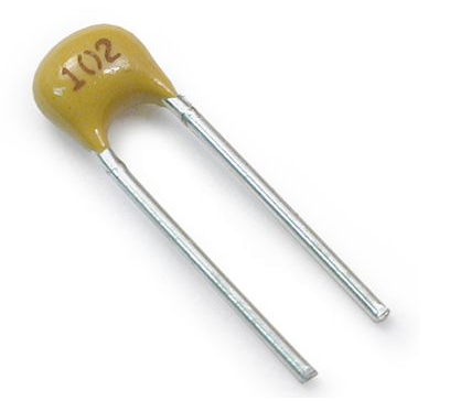
 The Capacitor Colour Code system was used for many years on unpolarised polyester and mica moulded capacitors. This system of colour coding is now obsolete but there are still many "old" capacitors around. Nowadays, small capacitors such as film or disk types conform to the BS1852 Standard and its new replacement, BS EN 60062, were the colours have been replaced by a letter or number coded system. The code consists of 2 or 3 numbers and an optional tolerance letter code to identify the tolerance. Where a two number code is used the value of the capacitor only is given in picofarads, for example, 47 = 47 pF and 100 = 100pF etc. A three letter code consists of the two value digits and a multiplier much like the resistor colour codes in the resistors section. For example, the digits 471 = 47*10 = 470pF. Three digit codes are often accompanied by an additional tolerance letter code as given below.


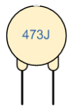
Consider the capacitor below:


The capacitor on the left is of a ceramic disc type capacitor that has the code 473J printed onto its body. Then the 4 = 1st digit, the 7 = 2nd digit,
the 3 is the multiplier in pico-Farads, pF and the letter J is the tolerance and this translates to:

   47pF * 1,000 (3 zero's) = 47,000 pF , 47nF or 0.047 uF 

 the J indicates a tolerance of +/- 5%


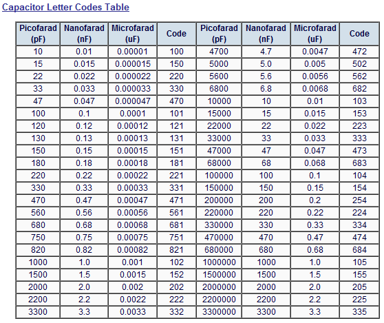
Then by just using numbers and letters as codes on the body of the capacitor we can easily determine the value of its capacitance either in Pico-farad's, Nano-farads or Micro-farads and a list of these "international" codes is given in the following table along with their equivalent capacitances.


Popular Posts